The mechanical system of the microscope. See what "Optical microscope" is in other dictionaries
The design of the microscope directly depends on its purpose. As you probably already guessed, microscopes are different, and an optical microscope will differ significantly from an electron or X-ray microscope. This article will discuss in detail the structure optical light microscope, which is on this moment is the most popular choice of amateurs and professionals, and with which you can solve many research problems.
Optical microscopes also have their own classification and may differ in their structure. However, there is a basic set of parts that are included in the device of any optical microscope. Let's look at each of these details.
In a microscope, optical and mechanical parts can be distinguished. The optics of a microscope includes objectives, eyepieces, and a lighting system. A tripod, a tube, an object table, fastenings of the condenser and light filters, mechanisms for adjusting the object table and the tube holder constitute the mechanical part of the microscope.
Let's start with perhaps optical part .
- Eyepiece. That part of the optical system that is directly connected with the eyes of the observer. In the simplest case, the lens consists of a single lens. Sometimes, for greater convenience, or, as they say, "ergonomics", the lens can be equipped, for example, with an "eyecup" made of rubber or soft plastic. Stereoscopic (binocular) microscopes have two eyepieces.
- Lens. Perhaps the most important part of the microscope, providing the main magnification. The main parameter is aperture, what it is is described in detail in the "Basic parameters of microscopes" section. Lenses are divided into "dry" and "immersion", achromatic and apochromatic, and even in cheap simple microscopes are a rather complex system of lenses. Some microscopes have unified lens mounting elements, which allows you to complete the device in accordance with the tasks and budget of the consumer.
- Illuminator. Very often, an ordinary mirror is used, which makes it possible to direct daylight onto the test sample. Currently, special halogen lamps are often used, which have a spectrum close to natural white light and not causing gross color distortions.
- Diaphragm. Basically, microscopes use so-called "iris" diaphragms, so named because they contain petals similar to those of an iris flower. By shifting or expanding the petals, you can smoothly adjust the strength of the light flux that enters the sample that is not being studied.
- Collector. With the help of a collector located near the light source, a light flux is created that fills the condenser aperture.
- Condenser. This element, which is a converging lens, forms a light cone directed at the object. The intensity of illumination is controlled by the aperture. Most microscopes use a standard two-lens Abbe condenser.
It is worth noting that in an optical microscope one of two main methods of illumination can be used: illumination of transmitted light and illumination of reflected light. In the first case, the light flux passes through the object, as a result of which an image is formed. In the second - light is reflected from the surface of the object.
A microscope is an optical instrument for studying objects invisible to the naked eye. In a microscope (Fig. 1), mechanical and optical parts are distinguished. The mechanical part of the device consists of a leg with a tube holder attached to it, on which the tube, eyepieces and objectives are attached (objectives are changed using a revolving device), an object stage and a lighting apparatus with a mirror. The tube is movably attached to the tube holder, it is raised and lowered with the help of two screws: a micrometric screw is used to pre-set the focus; micrometer screw - for fine focusing. The object table is equipped with a device that allows you to move the drug in different directions in the horizontal plane. The lighting apparatus consists of a condenser and a diaphragm, which are located between the mirror and the table.
Rice. 1. Biological microscope:
1 - eyepieces;
2 - binocular attachment;
3 - head for attaching a revolver with a seat for changing tubes;
4 - binocular attachment screw;
5 - revolver on a skid;
6 - lens;
7 - subject table;
8 and 9 - the lamb of the longitudinal (8) and transverse (9) movement of the preparation driver;
10 - aplanatic condenser for direct and oblique illumination;
11 - table centering screws;
12 - mirror;
13 - lamb micromechanism;
14 - condenser bracket;
15 - screw head fixing the upper part of the stage;
16 - box with micromechanism;
17 - leg;
18 - coarse screw;
19 - tube holder.
The diaphragm regulates the intensity of light entering the condenser. The condenser can be moved in a vertical direction, changing the intensity of the light flux entering the lens. Objectives are systems of mutually centered lenses that give a reverse magnified image of an object. The magnification of the lenses is indicated on the frame (X10, X20, X40, X90). Lenses come in two types: dry and immersion (submersible). The immersion lens is first lowered into the immersion oil with the help of a macroscrew under the control of the eye, and then, by manipulating the microscrew, a clear image of the object is achieved. The eyepiece is optical system, which magnifies the image taken in the lens. Eyepiece magnifications are indicated on the frame (X5, etc.). The total magnification of a microscope is equal to the magnification of the objective and the magnification of the eyepiece.
Rice. 2. Microscope MBI-1 with illuminator OI-19.
You can work with the microscope in daylight and artificial lighting, using a special lighting apparatus as a light source (Fig. 2). When working with a condenser, a flat mirror is used, regardless of the light source. They work with a concave mirror without a condenser. In daylight, the condenser is raised to the level of the object stage, in artificial light it is lowered until the light source appears in the plane of the preparation. See also Microscopic technique, Microscopy.
Posted on
INTRODUCTION
With the help of a digital microscope, an immersion into a mysterious and fascinating world takes place, where you can learn a lot of new and interesting things. Children, thanks to the microscope, better understand that everything living is so fragile and therefore you need to be very careful with everything that surrounds you. The digital microscope is a bridge between the real ordinary world and the microcosm, which is mysterious, unusual and therefore surprising. And everything amazing strongly attracts attention, affects the mind of the child, develops creativity, love for the subject, interest in the world around.
Children meet each task using a microscope with delight and curiosity. It turns out that it is very interesting for them to see in an enlarged form both cells, and human hair, and leaf veins, and fern spores, and the mold fungus mukor.
Chapter 1
A magnifying glass is the simplest magnifying device. Its main part is a magnifying glass, convex on both sides and inserted into a frame. With the help of a magnifying glass, we see an image of an object magnified 2-25 times. The magnifying glass is taken by the handle and brought closer to the object at such a distance at which the image of the object becomes the clearest.
A microscope is an instrument that magnifies the image of an object by hundreds or even thousands of times. The first microscopes began to be made in the 17th century. The most advanced at that time were microscopes designed by the Dutchman Anto-ni van Leeuwenhoek. His microscopes gave magnification up to 270 times. Modern light microscopes magnify the image up to 3600 times. In the XX century. The electron microscope was invented, magnifying the image by tens and hundreds of thousands of times.
The main part of the light microscope that you work with at school is the magnifying glasses inserted into the tube, or tube (in Latin, "tube" means "tube"). At the upper end of the tube is an eyepiece, consisting of a frame and two magnifying glasses. The name "ocular" comes from the Latin word "oculus", which means "eye". When examining an object with a microscope, the eye is brought closer to the eyepiece.
At the lower end of the tube is placed a lens consisting of a frame and several magnifying glasses. The name "objective" comes from the Latin word "objectum", which means "object".
The tube is attached to a tripod. An object table is also attached to the tripod, in the center of which there is a hole, and under it there is a mirror.
Using a microscope, you can examine the cells of all organs of the plant.
Prepare the preparation, place it on the object table and fix the glass slide there with two clamps.
Using the screw, smoothly lower the tube so that the lower edge of the lens is at a distance of 1-2 mm from the preparation.
Looking through the eyepiece, slowly raise the tube until a clear image of the object appears.
Put the microscope back in its case after use.
The microscope includes three main functional parts:
lighting part
Designed to create a light flux that allows you to illuminate the object in such a way that the subsequent parts of the microscope perform their functions with the utmost accuracy. The illuminating part of a transmitted light microscope is located behind the object under the objective in direct microscopes and in front of the object above the objective in inverted ones. The lighting part includes a light source (a lamp and an electric power supply) and an optical-mechanical system (collector, condenser, field and aperture adjustable / iris diaphragms).
playback part
Designed to reproduce an object in the image plane with the image quality and magnification required for research (i.e., to build such an image that reproduces the object as accurately as possible and in all details with the resolution, magnification, contrast and color reproduction corresponding to the microscope optics). The reproducing part provides the first stage of magnification and is located after the object to the image plane of the microscope.
The reproducing part includes a lens and an intermediate optical system.
Modern microscopes of the latest generation are based on optical systems of lenses corrected for infinity. This additionally requires the use of so-called tube systems, which “collect” parallel beams of light coming out of the objective in the image plane of the microscope.
visualizing part
Designed to obtain a real image of an object on the retina, film or plate, on the screen of a television or computer monitor with additional magnification (the second stage of magnification).
The imaging part is located between the image plane of the lens and the eyes of the observer (camera, camera). The imaging part includes a monocular, binocular or trinocular visual attachment with an observational system (eyepieces that work like a magnifying glass).
In addition, this part includes systems of additional magnification (systems of a wholesaler / change of magnification); projection nozzles, including discussion nozzles for two or more observers; drawing devices; image analysis and documentation systems with appropriate adapter (matching) elements.
Modern microscopeconsists of the following structural and technological parts:
optical;
mechanical;
electric.
The mechanical part of the microscope
The main structural and mechanical unit of the microscope is tripod. The tripod includes the following main blocks: base and tube holder.
Base is a block on which the entire microscope is mounted. In simple microscopes, illuminating mirrors or overhead illuminators are installed on the base. In more complex models, the lighting system is built into the base without or with a power supply.
Varieties of microscope bases
base with lighting mirror;
so-called "critical" or simplified lighting;
Keller illumination.
a lens change unit with the following versions - a revolving device, a threaded device for screwing in the lens, a "sled" for threadless mounting of lenses using special guides;
focusing mechanism for coarse and fine adjustment of the microscope for sharpness - a mechanism for focusing movement of lenses or tables;
attachment point for interchangeable object tables;
attachment point for focusing and centering movement of the condenser;
attachment point for interchangeable nozzles (visual, photographic, television, various transmitting devices).
Microscopes may use racks to mount nodes (for example, the focusing mechanism in stereo microscopes or the illuminator mount in some models of inverted microscopes).
The purely mechanical part of the microscope is object table, intended for fastening or fixing in a certain position of the object of observation. Tables are fixed, coordinate and rotating (centered and non-centered).
Microscope optics (optical part)
Optical components and accessories provide the main function of the microscope - the creation of an enlarged image of an object with a sufficient degree of reliability in terms of shape, size ratio of the constituent elements and color. In addition, the optics must provide an image quality that meets the objectives of the study and the requirements of the analysis methods.
The main optical elements of a microscope are the optical elements that form the illuminating (including the condenser), observational (eyepieces) and reproducing (including lenses) systems of the microscope.
microscope objectives
They are optical systems designed to build a microscopic image in the image plane with the appropriate magnification, resolution of the elements, fidelity in the shape and color of the object of study. They have a complex optical-mechanical design, which includes several single lenses and components glued from 2 or 3 lenses. The number of lenses is determined by the range of tasks solved by the lens. The higher the image quality given by the lens, the more complex its optical design. The total number of lenses in a compound lens can be up to 14 (for example, this could be a plan apochromat lens with a magnification of 100x and a numerical aperture of 1.40).
The lens consists of frontal and subsequent parts. The frontal lens (or lens system) is facing the preparation and is the main one when building an image of the appropriate quality, determines the working distance and the numerical aperture of the lens. The subsequent part in combination with the front provides the required magnification, focal length and image quality, and also determines the height of the objective and the length of the microscope tube.
Lens classification
The classification of lenses is much more complicated than the classification of microscopes. Lenses are divided according to the principle of calculated image quality, parametric and constructive-technological features, as well as research and contrast methods.
According to the principle of calculated image quality lenses can be:
achromatic;
apochromatic;
flat field lenses (plan).
Achromatic lenses.
Achromatic lenses are designed for use in the spectral range 486-656 nm. Correction of any aberration (achromatization) is performed for two wavelengths. These lenses eliminate spherical aberration, positional chromatic aberration, coma, astigmatism, and partially spherochromatic aberration. The image of the object has a slightly bluish-reddish tint.
Apochromatic objectives.
Apochromatic objectives have an extended spectral region and achromatization is performed for three wavelengths. At the same time, in addition to position chromatism, spherical aberration, coma and astigmatism, the secondary spectrum and spherochromatic aberration are also corrected quite well due to the introduction of lenses made of crystals and special glasses into the scheme. Compared to achromats, these lenses typically have larger numerical apertures, produce sharper images, and accurately reproduce the color of an object.
Semi-apochromats or microfluaries.
Modern lenses with intermediate image quality.
plan lenses. In plan lenses, the curvature of the image along the field has been corrected, which ensures a sharp image of the object throughout the entire field of observation. Plan lenses are usually used for photography, and the use of plan apochromats is most effective.
The need for this type of lenses is growing, but they are quite expensive due to the optical design that implements a flat image field and the optical media used. Therefore, routine and working microscopes are equipped with so-called economic objectives. These include lenses with improved image quality across the field: achrostigmata (LEICA), CP-achromats and achroplanes (CARL ZEISS), stigmachromats (LOMO).
By parametric features lenses are divided as follows:
lenses with a finite tube length (for example, 160 mm) and lenses corrected for the length of the tube "infinity" (for example, with an additional tube system having a focal length of 160 mm);
small lenses (up to 10x); medium (up to 50x) and large (more than 50x) magnifications, as well as lenses with extra high magnification (over 100x);
objectives of small (up to 0.25), medium (up to 0.65) and large (more than 0.65) numerical apertures, as well as objectives with increased (compared to conventional) numerical apertures (for example, apochromatic correction objectives, as well as special objectives for fluorescent microscopes);
objectives with increased (compared to conventional) working distances, as well as with large and extra long working distances (objectives for work in inverted microscopes). The working distance is the free distance between the object (the plane of the coverslip) and the bottom edge of the frame (lens if protruding) of the frontal lens component;
lenses providing observation within a normal linear field (up to 18 mm); wide-field lenses (up to 22.5 mm); ultra-wide-field lenses (more than 22.5 mm);
lenses are standard (45 mm, 33 mm) and non-standard in height. Height - the distance from the reference plane of the lens (the plane of contact of the screwed-in lens with the revolving device) to the plane of the object with a focused microscope, is a constant value and ensures the parfocality of a set of lenses of different magnifications, similar in height, installed in the revolving device. In other words, if a sharp image of an object is obtained with the help of a lens of one magnification, then when moving to subsequent magnifications, the image of the object remains sharp within the depth of field of the lens.
By constructive and technological features there is the following division:
lenses with and without a spring-loaded frame (starting with a numerical aperture of 0.50);
lenses having an iris diaphragm inside to change the numerical aperture (for example, in lenses with an increased numerical aperture, in transmitted light lenses for implementing the dark field method, in polarized reflected light lenses);
lenses with a corrective (control) frame, which provides the movement of optical elements inside the lens (for example, to correct the image quality of the lens when working with different thicknesses of the coverslip or with different immersion liquids; as well as to change the magnification during a smooth - pancratic - change of magnification) and without her.
To provide methods of research and contrasting Lenses can be divided as follows:
objectives working with and without cover glass;
lenses of transmitted and reflected light (reflexless); luminescent lenses (with a minimum of intrinsic luminescence); polarizing lenses (without glass tension in optical elements, that is, without introducing their own depolarization); phase lenses (having a phase element - a translucent ring inside the lens); lenses DIC (DIC), working on the method of differential interference contrast (polarizing with a prism element); epi-objectives (reflected light objectives designed to provide bright and dark field methods have specially designed lighting epi-mirrors in their design);
immersion and non-immersion lenses.
Immersion (from Latin immersio - immersion) is a liquid that fills the space between the object of observation and a special immersion lens (condenser and glass slide). Three types of immersion liquids are mainly used: oil immersion (MI/Oil), water immersion (VI/W) and glycerol immersion (GI/Glyc), the latter being mainly used in ultraviolet microscopy. Immersion is used in cases where it is required to increase the resolution of a microscope or its application is required by the technological process of microscopy. In this case, the following occurs: 1. increased visibility due to an increase in the difference between the refractive index of the medium and the object;
2. increasing the depth of the viewed layer, which depends on the refractive index of the medium.
In addition, the immersion liquid can reduce the amount of stray light by eliminating glare from the object. This eliminates the inevitable loss of light when it enters the lens.
immersion lenses. The image quality, parameters and optical design of immersion objectives are calculated and selected taking into account the thickness of the immersion layer, which is considered as an additional lens with an appropriate refractive index. The immersion liquid placed between the object and the front lens component increases the angle at which the object is viewed (aperture angle). The numerical aperture of the immersion-free (dry) objective does not exceed 1.0 (resolution is about 0.3 µm for the main wavelength); immersion - reaches 1.40, depending on the refractive index of immersion and the technological capabilities of manufacturing the front lens (the resolution of such a lens is about 0.12 microns).
High magnification immersion lenses have a short focal length - 1.5-2.5 mm with a free working distance of 0.1-0.3 mm (distance from the preparation plane to the frame of the front lens of the objective).
Eyepieces
Optical systems designed to build a microscopic image on the retina of the observer's eye. In general, eyepieces consist of two groups of lenses: the eye lens, which is closest to the observer's eye, and the field lens, which is closest to the plane in which the lens builds an image of the object in question.
Eyepieces are classified according to the same groups of characteristics as lenses: 1. eyepieces of compensatory (K - compensate for the chromatic difference in magnification of lenses over 0.8%) and non-compensated action; 2. normal and flat field eyepieces; 3. wide-angle eyepieces (with an eyepiece number - the product of the eyepiece magnification and its linear field - more than 180); ultra wide-angle (with an eyepiece number of more than 225); 4. eyepieces with extended pupil for work with and without glasses; 5. observation eyepieces, projection eyepieces, photo eyepieces, gamals; 6. eyepieces with internal aiming (with the help of a movable element inside the eyepiece, adjustment is made to a sharp image of the grid or the image plane of the microscope; as well as a smooth, pancratic change in the eyepiece magnification) and without it.
Lighting system
The illumination system of the microscope is a system of lenses, diaphragms and mirrors (the latter are used if necessary), which provides uniform illumination of the object and complete filling of the objective aperture.
The illumination system of a transmitted light microscope consists of two parts - a collector and a condenser.
Collector. With a built-in transmitted light illumination system, the collector part is located near the light source at the base of the microscope and is designed to increase the size of the luminous body. To ensure tuning, the collector can be made movable and move along the optical axis. Near the collector is the field diaphragm of the microscope.
Condenser. The optical system of the condenser is designed to increase the amount of light entering the microscope. The condenser is located between the object (subject table) and the illuminator (light source). Most often, in educational and simple microscopes, the condenser can be made non-removable and motionless. In other cases, the condenser is a removable part and, when adjusting the illumination, has a focusing movement along the optical axis and a centering movement perpendicular to the optical axis.
The condenser always has an illuminating aperture iris diaphragm.
The condenser is one of the main elements that ensure the operation of the microscope in various methods of illumination and contrast:
oblique illumination (diaphragm from the edge to the center and displacement of the illumination aperture diaphragm relative to the optical axis of the microscope);
dark field (maximum aperture from the center to the edge of the illumination aperture);
phase contrast (annular illumination of the object, while the image of the light ring fits into the phase ring of the lens).
Classification of condensers it is close in groups of characteristics to lenses: 1. condensers are divided into non-achromatic, achromatic, aplanatic and achromatic-aplanatic in terms of image quality and type of optical correction; 2. condensers of small numerical aperture (up to 0.30), medium numerical aperture (up to 0.75), large numerical aperture (over 0.75); 3. condensers with regular, long and extra long working distance; 4. ordinary and special condensers for various methods of research and contrasting;
5. The design of the condenser is a single one, with a folding element (frontal component or large field lens), with a screwed-in frontal element.
Abbe condenser- a condenser not corrected for image quality, consisting of 2 non-achromatic lenses: one is biconvex, the other is plano-convex, facing the object of observation (the flat side of this lens is directed upwards). Condenser aperture A = 1.20. Has an iris diaphragm.
Aplanatic condenser- a condenser consisting of three lenses arranged as follows: the upper lens is plano-convex (the flat side is directed towards the objective), followed by concave-convex and biconvex lenses. Corrected for spherical aberration and coma. Condenser aperture A = 1.40. Has an iris diaphragm.
Achromatic condenser- condenser fully corrected for chromatic and spherical aberration.
Condenserdark field- a condenser designed to produce a dark field effect. It can be custom-made or converted from an ordinary bright-field condenser by installing an opaque disk of a certain size in the plane of the iris diaphragm of the condenser.
Chapter 2. DIGITAL MICROSCOPE AND ITS APPLICATION IN BIOLOGY LESSONS
In today's digital world, optical microscopes are considered obsolete and have been replaced by digital counterparts. This provides both advantages and disadvantages. But, undoubtedly, digital microscopes have greater potential and opportunities, which any student can now use.
Microscope - a laboratory optical system for obtaining enlarged images of small objects for the purpose of examination, study and practical application. The combination of manufacturing technologies and the practical use of microscopes is called microscopy.
With the help of microscopes, the shape, size, structure and many other characteristics of micro-objects, as well as the microstructure of macro-objects, are determined.
The history of the creation of the microscope as a whole took a lot of time. Gradually, the development of optical technology has led to the emergence of better lenses, more accurate holding devices.
By the end of the 20th century, optical microscopes had reached the pinnacle of their development. The next step was the emergence of digital microscopes, in which the lens was replaced by a digital camera.
Actually, the main difference between a digital microscope and a conventional one is the absence of an eyepiece through which an object is observed by the human eye. Instead, a digital camera is installed, firstly, it does not give distortion (the number of lenses is reduced), and secondly, color reproduction improves, and images are obtained in digital form, which allows for additional post-processing, as well as storing huge arrays of photographs on just one hard drive.
magnifying instrument microscope biology
The digital microscope Digital Blue QX5 is adapted for work in school conditions. It is equipped with a visual-to-digital information converter, which provides real-time transmission of an image of a micro-object and micro-process to a computer, as well as their storage, including in the form of digital video recording. The microscope has a simple structure, USB-interface, two-level illumination. Included with it was software with a simple and intuitive interface.
With modest, from a modern point of view, system requirements, it allows you to:
Magnify the studied objects placed on the stage by 10, 60 and 200 times (the transition is carried out by turning the blue drum)
Use both transparent and opaque objects, both fixed and non-fixed
Examine the surfaces of sufficiently large objects that do not fit directly on the stage
Take pictures, as well as make a video of what is happening by pressing the appropriate button inside the program interface
Record the observed without worrying about its safety at this moment - the files are automatically placed on the hard drive of the computer.
Set shooting parameters by changing the frame rate - from 4 frames per second to 1 per hour
Make the simplest changes in the received photographs without leaving the microscope program: apply signatures and indexes, copy parts of the image, and so on.
Export results for use in other programs:
graphic files - in *.jpg or *.bmp formats, and video files - in *.avi format
Collect from the results of photo and video shooting demonstration collections - "filmstrips" (the program memory can simultaneously store 4 sequences, including up to 50 objects each). Subsequently, a selection of frames, temporarily unused, can be easily disassembled, since the graphic files remain on the hard drive of the computer
Print the resulting graphic file in three different modes:
9 thumbnails on A4 sheet, whole A4 sheet, enlarged image split into 4 A4 sheets
Demonstrate the objects under study and all actions performed with them on a personal computer monitor and / or on a projection screen, if a multimedia projector is connected to the computer
What does a digital microscope give a teacher and a student in relation to biology lessons?
One of the biggest challenges facing a biology teacher when doing lab work with a traditional microscope is the almost non-existent ability to understand what his students are really seeing. How many times do guys call for something that is not at all what is needed - in the field of view is either the edge of the preparation, or an air bubble, or a crack ...
It is good if there is a permanent laboratory assistant or trained public assistants to carry out such obligatory work under the program. And if you are alone - for 25 people and 15 microscopes? And the microscope standing in the middle of the desk (one for two!) cannot be moved - otherwise, all the light and sharpness settings go astray, while the results of the work (as well as time and interest) are lost.
The same classes are much easier and more efficient if the laboratory work is preceded by an introductory briefing conducted using a digital microscope.
In this case, the actions with the preparation actually performed and simultaneously demonstrated through the projector and the resulting image are the best helpers.
They visually show the student the correct course of action and the expected result. The sharpness of the image in the computer version of the microscope is also achieved by turning the screws.
It is also important that you can indicate and sign the parts of the drug, collecting a slide show from these frames.
You can do this both immediately in the lesson, and in the process of preparing for it.
After such an introductory briefing, laboratory work using traditional optical microscopes becomes easier and more efficient.
If you do not have magnifiers, then this microscope can be used as a binocular (10 or 60 times magnification). The objects of study are flower parts, leaf surfaces, root hairs, seeds or seedlings. And molds - even mucor, even penicillium? For arthropods, these are all their interesting parts: legs, antennae, mouthparts, eyes, covers (for example, scales of butterfly wings). For chordates - fish scales, bird feathers, wool, teeth, hair, nails, and much, much more. This is far from a complete list.
It is also important that many of these objects will remain alive after examination organized using a digital microscope: insects - adults or their larvae, spiders, mollusks, worms can be observed by placing them in special Petri dishes (there are two of them in the set with each microscope). + tweezers, pipette, 2 jars with lids for collecting material). And any indoor plant, brought in a pot at a distance of about 2 meters to the computer, easily becomes an object of observation and research, without losing a single leaf or flower. This is possible due to the fact that the upper part of the microscope is removable, and when brought to the object, it works like a webcam, giving a 10x magnification. The only inconvenience is that focusing is carried out only by tilting and zooming in and out.
But, having caught the right angle, you can easily take a photo without reaching for the computer - right on the part of the microscope that is in your hands, there is the necessary button: press once - you get a photo, press and hold - a video is taken.
The quality of graphic files obtained using a digital microscope
leaf epidermis
The epidermis of the leaf is the integumentary tissue of the leaf, otherwise it is called the skin. It is formed by a single layer of flat cells that fit snugly together. These cells under the microscope appear light, transparent due to the fact that a significant volume in them is occupied by the central vacuole filled with cell sap. The vacuole pushes the nucleus and all cellular organelles to the periphery of the cell. However, the nucleus is clearly visible in every cell, it stores all hereditary information. Chloroplasts are usually absent in the main cells of the leaf epidermis. Among the main skin cells, cells of a different shape stand out; they lie in pairs, forming stomata. Each stomata consists of two bean-shaped guard cells, and between these cells there is a gap in the form of a lens. This gap is called the stomatal gap and is the intercellular space. The shape of the stomatal fissure and its size can vary depending on how tightly the guard stomatal cells adjoin each other. In the guard stomatal cells, the nucleus can be seen, and chloroplasts are always present in them, carrying out the process of photosynthesis. From the outer surface, each cell of the skin of the leaf is covered with a special protective layer - the cuticle. The cuticle can be thick and tough. It may contain fat-like substances and wax. The cuticle must be transparent so as not to prevent the penetration of sunlight to the internal tissues of the leaf, where the process of photosynthesis is actively taking place. The epidermis plays a very important role in the life of the leaves. It protects the sheet from damage and drying out. Through the open stomata, air enters the leaf, it is necessary for respiration and photosynthesis. Also, through the open stomatal gaps, oxygen is released, which is formed during photosynthesis, and water vapor. If the plant experiences a lack of water, for example, in hot, dry weather, then the stomatal gaps close. So the plant protects itself from excessive water loss. At night, the stomata are also usually closed.
seed germ
The germ is the most important part of the seed. In fact, it is a microscopic plant that has all the organs: an embryonic shoot with an embryonic stem, embryonic leaves and an embryonic apical bud, as well as an embryonic root. On the preparation, the germinal shoot is directed in one direction, the germinal root is oriented strictly opposite. In the area between the germinal bud, covered with germinal leaves, and the root is the germinal stem. The cotyledon adjoins the embryo directly on one side. Its cells have the same staining intensity as stem cells. The cotyledon is a special leaf of the embryo. Cotyledons protect the germinal bud, appearing first on the soil surface. One cotyledon is visible on the preparation, therefore, this embryo belongs to monocotyledonous plants. The seed germ is best viewed under a low magnification microscope so that it can fit in the entire field of view of the microscope.
onion peel
The bulb is a modified shoot with a short flat stem (bottom) and fleshy, juicy leaves with scales. Therefore, the onion skin is the epidermis of the leaf, which develops in the dark without access to light, as a result of which chloroplasts are absent in the cells of the onion skin. Instead of chloroplasts, these cells have colorless plastids - leukoplasts. Onion skin cells have an elongated shape, close to rectangular. Cell borders are clearly visible, they are represented by transparent membranes, hard enough to maintain the shape of the cells. Through cell membranes, water can be transferred from cell to cell, as well as substances dissolved in water. The cells look light transparent due to the fact that a large central vacuole with cell sap occupies a significant volume of them. The vacuole is the place where water is stored in the cell. It can contain in dissolved form reserve nutrients, pigments, solutions of organic acids, mineral salts and various waste products of a plant cell. The vacuole pushes the nucleus and cytoplasm to the periphery of the cell, while the cytoplasm is divided into separate strands. The strands of the cytoplasm are detected under a microscope at high magnification in the form of narrow ribbons extending in rays from the nucleus. In the strands of the cytoplasm, granular structure is manifested, which is associated with the presence of various organelles in the cytoplasm.
root cap
The top of the root is elongated into a cone and directed towards the center of the Earth. It is protected by a root cap, which is a cap at the top of the root. It consists of several layers of cells. These cells play a very important role in deepening the root into the soil. From the surface of the cap, the cells are sloughed off, while mucus is released, which lubricates the soil and ensures the root slides in depth. From the inner surface of the root cap there is a constant replenishment of cells. With its inner surface, the root cap adjoins the very apical part of the root, where cell division is constantly taking place, that is, the educational tissue is located. Due to the educational tissue of the root tip, there is a constant replenishment of the cells of the root cap. On the preparation, the zone of the root cap differs well from the root apex. The root cap in the form of a crown frames the educational zone of the root. The cells in it lie more loosely than at the top of the pilus. The outer edge is uneven due to listening cells. The thickness of the layer of the root cap in the most voluminous place is several tens of cells.
pollen of a flowering plant
The pollen is produced inside the anther of the stamen of a flowering plant. Mature pollen takes part in the process of pollination, that is, it is transferred from the stamens to the stigma of the pistil. If pollination does not occur, no fruit will form. Pollen is carried by the wind or by insects, depending on which pollination the flower is adapted to. Pollen can be transferred to the pistil stigma of the same flower where it matured (self-pollination), to the pistil stigma of other flowers of the same plant, and to the pistil stigma of flowers of other plants of the same species (cross-pollination). When analyzed under a microscope, pollen is revealed in the form of grains with a pronounced morphology. The surface of a dust grain is covered with a complex protective shell, on which protrusions or tubercles of various shapes can be detected. These structures are the morphological species trait of the plant. Under the shells of pollen grains are living cells. One cell is called vegetative. When a pollen grain germinates, hitting the stigma of a pistil, it forms a pollen tube. pollen tube
Ministry of Education Russian Federation Mari State Technical University Department: RtiMBS Application of lasers in biology and medicine.
Flowering or angiosperms are the most highly organized among plants. The study of plants on different levels their biological organization: cells, tissues, organs. Functions and structure of the seed, shoot, stem, bud. Description of the process of photosynthesis.
Characteristics of the stages of development and possibilities of fluorescence microscopy. Detection methods physiological state microalgae cells. Quantitative registration of fluorescence intensity. Determination of vitamin content in plant cells.
Methods for studying the morphology of microorganisms. Rules of work in the microbiological laboratory. Microscopy in a bright field. Installation of light according to Koehler. Images of fixed preparations obtained as a result of the study of the morphology study method.
The history of cell research, the most notable works of all times, written on the topic and modern knowledge. The elementary structure of the cell, its main components and their functions. Cytoplasm and its organelles, the purpose of the Golgi complex and inclusions.
STRUCTURE OF THE MICROSCOPE AND RULES OF WORKING WITH IT
The microscopic method (gr. micros - the smallest, scoreo - I look) allows you to study the structure of the cell using microscopes (light, phase-contrast, luminescent, ultraviolet, electronic). With light microscopy, an object is viewed in the rays visible light. For this, microscopes such as MBR, MBI, MBS-1, R-14, MIKMED - 1, etc. are used.
The microscope consists of mechanical, lighting and optical parts.
To mechanical part microscopes include: tripod stand (shoe), tripod column (tube holder), tube, object table with terminals or clamps of the preparation, sorting screws (screws for moving the object stage and preparation), revolver, macro- and micrometric screws, condenser screw, iris lever diaphragms, frames for light filters. Sorting screws are used to center the object on the preparation. The revolver consists of two ball segments connected to each other by a central screw. The upper segment of the ball is attached to the tube. In the lower segment there are holes for screwing in lenses. Macro- and micrometric screws provide coarse and micrometric focusing (change the distance between the lens and the object under study).
lighting part consists of a movable mirror, iris diaphragm, condenser and light filters (opaque and blue). The mirror serves to capture light and direct it to the preparation (object). The mirror has two surfaces - flat and concave. The flat surface of the mirror is used in bright light, the concave surface is used in low light. The diaphragm consists of a system of metal plates, which, due to the movement of the lever, can converge towards the center or diverge. The diaphragm is located under the condenser and serves to change the width of the light beam. The condenser (lens system) concentrates scattered light rays into a thin beam of parallel rays and directs them to the object. It moves up and down with a special screw, which allows you to set the optimal illumination of the preparation. The normal position of the condenser is the highest. Light filters eliminate the diffraction of light. They are located in a special folding frame, located under the iris diaphragm. Matte filter is used in diffused light, blue - in bright light.
Magnifiers: microscope MBR-1 and microscope R-14.
Mechanical part: 1 - tripod stand (base); 2 - tripod column (tube holder); 3 - tube; 4 - revolver; 5 - subject table; 6 - sorting screws; 7 - macrometric screw; 8 - micrometer screw; 9 - condenser screw; 10 - iris-diaphragm lever, 11 - frame for light filters.
lighting part: 12 - mirror; 13 - diaphragm; 14 - condenser.
Optical part: 15 - eyepiece; 16 - lenses.
Optical part consists of objectives (a system of lenses facing the object) that are located in the sockets of the revolver, and eyepieces (a system of lenses facing the eye of the researcher). The eyepieces are inserted into the top hole of the tube. Usually, microscopes are equipped with three objectives (8x - low magnification objective, 40x - high magnification objective, 90x - immersion objective). In accordance with this, the lens is marked 8, 40 or 90. The eyepieces also have a marking indicating their magnification. Most often, eyepieces with a magnification of 7, 10 and 15 times are used.
The total magnification of the microscope (a value showing how many times the linear dimensions of the image are greater than the linear dimensions of the object) is equal to the product of the magnifications of the eyepiece and objective. For example, when working with a 10x eyepiece and an 8x objective, the linear dimensions of the object increase by 80 times (8 x 10 = 80).
The most important characteristic of a light microscope is its resolution. Resolution (d) is the minimum distance between two points of an object that can be seen separately. It is determined by the formula:
d = 0.61 _________________
where λ is the wavelength of light, n is the refractive index of the medium between the object and the lens, α is the angle between the optical axis of the lens and the most deflected beam entering the lens. The value of "n sin α" is called the numerical aperture of the lens. For an 8x lens, it is 0.20; for the "40x" lens - 0.65; the lens "90x" - 1.25. The resolution limit of a microscope depends on the wavelength of the light source. In a light microscope, it is equal to 555 nm. Therefore, modern optical microscopes have a useful magnification limit of up to 1500 times.
Rules for working with a microscope at low magnification (lens 8x).
1. Before starting work, check the functionality of the microscope, wipe the lenses of the eyepiece, objectives, condenser and mirror with a napkin. It is forbidden to unscrew eyepieces and objectives.
2. Place the microscope at the workplace on the left, a palm's width from the edge of the table, with the tube holder towards you and the object table away from you.
3. Raise the condenser and place it at the level of the object table, open the diaphragm.
4. With the movement of the revolver, bring the lens of low magnification “8x” to a click (a click indicates that the optical axis of the eyepiece
and lenses match).
5. Rotate the macrometer screw to position the 8x objective 1 cm from the stage.
6. Illuminate the field of view: looking into the eyepiece, turn the mirror large and index fingers one or both hands in relation to the light source until the entire field of view is illuminated evenly and sufficiently intensely. Place your fingers on the side of the mirror so that they do not cover the mirror itself. From now on, the microscope must not be moved in the workplace.
7. Take the preparation from the histological box with the thumb and forefinger by side surfaces slide glass. Check where the front side of the preparation is (on the front side there is a coverslip). Examine the drug in the light. Determine the location of the object. Place the specimen on the microscope stage face up so that the object itself is in the center of the opening of the microscope stage.
8. Looking from the side, using a macrometric screw, lower the low magnification lens to a distance of 0.5 cm from the preparation, i.e. below the focal length.
9. Looking into the eyepiece, by moving the macrometric screw towards yourself, smoothly raise the tube up until a clear image of the object appears.
10. With the help of sorting screws or smooth movements of the fingers, bring the object, or the part of the object of interest to us, to the center of the field of view, and then proceed to study the preparation and sketch it in an album.
11. At the end of the study of the preparation, use a macrometric screw to raise the objective "8x" by 2 - 3 cm. Remove the preparation from the object table and put it in the histological box.
12. At the end of the work, put a napkin on the stage, lower the "8x" lens down at a distance of 0.5 cm from the stage. Cover the microscope with a cover and put it in its place of storage. When carrying the microscope, it is necessary to hold the microscope by the tripod with one hand, and support the mirror from below with the other.
Rules for working with a microscope at high magnification (lens 40x).
1. When working with a microscope at high magnification, you must first follow all the points of the rules for working with an "8x" lens (see points 1 - 10).
2. After finding the object at a low magnification, it is necessary to bring the part of interest to us exactly to the center of the field of view using sorting screws (when switching to a high magnification, the diameter of the front lens of the objective decreases by 5 times, so if you do not center it, the object may be outside the field of view).
3. Using a macrometric screw, raise the lens up by 2 - 3 cm and use a revolver to replace the "8x" lens with the "40x" lens.
4. Looking from the side, lower the “40x” lens with a macrometric screw so that the distance between it and the preparation is 1 mm, i.e. the lens is below the focal length.
5. Looking into the eyepiece, gently lift the tube up with a macrometric screw until an image of the object appears.
6. Additional focusing is carried out using a micrometer screw, which can be rotated forward or backward no more than half a turn.
7. Study the drug. Sketch.
8. At the end of the study of the preparation with a macrometric screw, raise the "40x" lens up to 2-3 cm. Remove the preparation from the table and put it in a histological box. By turning the revolver, replace the “40x” objective with the “8x” objective, put a napkin on the object table.
FROM using the macrometric screw, lower the “8x” objective to a distance of 0.5 cm. Close the microscope with a cover and put it in its storage place.
Working with an immersion lens (90s lens).
The "90x" lens is used when working with very small and thin objects. The space between the objective and the preparation is filled with a special immersion oil. Oil has a refractive index approaching that of glass, so light rays enter the lens without being refracted or changing direction as they pass through. various environments. The immersion objective requires careful handling as its front lens has a small
focal length and rough work can damage both the lens and the preparation.
1. Before you start working with the 90x lens, you need to find the object at 56x and then 280x. Accurately bring the part of the object of interest to the center of the field of view using sorting screws, because. must be remembered inverse relationship between the power of magnification and the diameter of the front lens.
2. Using a macrometric screw, raise the "40x" lens up by 2-3 cm. Apply a drop of immersion oil with a glass rod to the area under study. The drop should not be very large or very small. Using a revolver, replace the "40x" lens with the "90x" lens.
3. Looking from the side, use a macrometric screw to lower the 90x objective into a drop of oil almost until it touches the cover slip, i.e. below the focal length.
4. Looking into the eyepiece, gently raise the “90x” objective with a macrometric screw until an image appears.
5. Using a micrometer screw, achieve a clear image of the object; start studying it and sketching it into an album (if necessary).
6. After completing the study of the preparation, use a macrometric screw to raise the objective "90x" up to 2-3 cm above the table. Remove the preparation, wipe off the oil with a strip of filter paper and wipe with a napkin. The drug is placed in a histological box. Also wipe the lens of the "90x" lens with a strip of filter paper, and then with a napkin. In case of severe contamination, when the oil dries, it is recommended to wipe the lens with a cloth moistened with gasoline.
7. Using a revolver, replace the "90x" lens with the "8x" lens. Put a napkin on the subject table. Using a macrometric screw, lower the “8x” objective down to a distance of 0.5 cm from the object stage. Close the microscope with a cover and put it in a place of permanent storage.
Prepared by: associate professor Logishinets I.A.
Literature:
1. Bekish O.-Ya.L., Nikulin Yu.T. Workshop on biology (for 1st year students of the Faculty of Pharmacy). - Vitebsk, 1997. - 90p.
2. http://wikipedia.ru
In Vasily Shukshin's story "The Microscope", the village carpenter Andrey Yerin bought his lifelong dream - a microscope - with his wife's salary, and set himself the goal of finding a way to exterminate all microbes on earth, since he sincerely believed that, without them, a person could to live more than one hundred and fifty years. And only an unfortunate misunderstanding prevented him from doing so. noble cause. For people of many professions, a microscope is a necessary equipment, without which it is simply impossible to perform many research and technological operations. Well, in "home" conditions, this optical device allows everyone to expand the boundaries of their capabilities by looking into the "microcosm" and exploring its inhabitants.
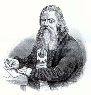
The first microscope was designed by no means by a professional scientist, but by an "amateur", a manufactory merchant Anthony Van Leeuwenhoek, who lived in Holland in the 17th century. It was this inquisitive self-taught person who was the first to look through a device he made by himself at a drop of water and saw thousands of the smallest creatures, which he called the Latin word animalculus (“little animals”). During his life, Leeuwenhoek managed to describe more than two hundred species of "animals", and by studying thin sections of meat, fruits and vegetables, he discovered the cellular structure of living tissue. For services to science, Leeuwenhoek was elected a full member of the Royal Society in 1680, and a little later became an academician of the French Academy of Sciences.
Leeuwenhoek's microscopes, of which he personally made more than three hundred in his life, were a small, pea-sized, spherical lens inserted into a frame. Microscopes had an object stage, the position of which relative to the lens could be adjusted with a screw, but these optical instruments was not - they had to be held in their hands. From the point of view of today's optics, the instrument called "Levenhoek's microscope" is not a microscope, but a very powerful magnifying glass, since its optical part consists of only one lens.
Over time, the device of the microscope has evolved markedly, microscopes of a new type have appeared, research methods have been improved. However, work with an amateur microscope to this day promises many interesting discoveries for both adults and children.
Microscope device
A microscope is an optical instrument designed to study magnified images of micro-objects that are invisible to the naked eye.
The main parts of a light microscope (Fig. 1) are an objective and an eyepiece enclosed in a cylindrical body - a tube. Most models designed for biological research come with three lenses with different focal lengths and a swivel mechanism designed for quick change - a turret, often called a turret. The tube is located on the top of a massive stand, including the tube holder. Slightly below the objective (or turret with multiple objectives) is a stage on which slides with test specimens are placed. Sharpness is adjusted using a coarse and fine adjustment screw, which allows you to change the position of the stage relative to the objective.
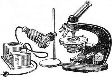
In order for the sample under study to have sufficient brightness for comfortable observation, the microscopes are equipped with two more optical units (Fig. 2) - an illuminator and a condenser. The illuminator creates a stream of light that illuminates the test preparation. In classical light microscopes, the design of the illuminator (built-in or external) involves a low-voltage lamp with a thick filament, a converging lens, and a diaphragm that changes the diameter of the light spot on the sample. The condenser, which is a converging lens, is designed to focus the illuminator beams on the sample. The condenser also has an iris diaphragm (field and aperture), which controls the intensity of illumination.
When working with light-transmitting objects (liquids, thin sections of plants, etc.), they are illuminated by transmitted light - the illuminator and condenser are located under the object table. Opaque samples should be illuminated from the front. To do this, the illuminator is placed above the object stage, and its beams are directed to the object through the lens using a translucent mirror.
The illuminator may be passive, active (lamp), or both. The simplest microscopes do not have lamps to illuminate samples. Under the table they have a double-sided mirror, in which one side is flat and the other is concave. In daylight, if the microscope is near a window, you can get pretty good illumination using a concave mirror. If the microscope is in a dark room, a flat mirror and an external illuminator are used for illumination.
The magnification of a microscope is equal to the product of the magnification of the objective and the eyepiece. With an eyepiece magnification of 10 and an objective magnification of 40, the total magnification factor is 400. Usually, objectives with a magnification of 4 to 100 are included in a research microscope kit. A typical microscope objective kit for amateur and educational research (x4, x10 and x40), provides increase from 40 to 400.
Resolution is another important characteristic of a microscope, which determines its quality and the clarity of the image it forms. The higher the resolution, the more fine details can be seen at high magnification. In connection with resolution, one speaks of "useful" and "useless" magnification. “Useful” is the maximum magnification at which the maximum image detail is provided. Further magnification (“useless”) is not supported by the resolution of the microscope and does not reveal new details, but it can adversely affect the clarity and contrast of the image. Thus, the limit of useful magnification of a light microscope is not limited by the overall magnification factor of the objective and the eyepiece - it can be made arbitrarily large if desired - but by the quality of the optical components of the microscope, that is, the resolution.
The microscope includes three main functional parts:
1. Lighting part
Designed to create a light flux that allows you to illuminate the object in such a way that the subsequent parts of the microscope perform their functions with the utmost accuracy. The illuminating part of a transmitted light microscope is located behind the object under the objective in direct microscopes and in front of the object above the objective in inverted ones.
The lighting part includes a light source (a lamp and an electric power supply) and an optical-mechanical system (collector, condenser, field and aperture adjustable / iris diaphragms).
2. Playback part
Designed to reproduce an object in the image plane with the image quality and magnification required for research (i.e., to build such an image that reproduces the object as accurately as possible and in all details with the resolution, magnification, contrast and color reproduction corresponding to the microscope optics).
The reproducing part provides the first stage of magnification and is located after the object to the image plane of the microscope. The reproducing part includes a lens and an intermediate optical system.
Modern microscopes of the latest generation are based on optical systems of lenses corrected for infinity.
This additionally requires the use of so-called tube systems, which “collect” parallel beams of light coming out of the objective in the image plane of the microscope.
3. Visualizing part
Designed to obtain a real image of an object on the retina, film or plate, on the screen of a television or computer monitor with additional magnification (the second stage of magnification).
The imaging part is located between the image plane of the lens and the eyes of the observer (camera, camera).
The imaging part includes a monocular, binocular or trinocular visual attachment with an observation system (eyepieces that work like a magnifying glass).
In addition, this part includes systems of additional magnification (systems of a wholesaler / change of magnification); projection nozzles, including discussion nozzles for two or more observers; drawing devices; image analysis and documentation systems with appropriate matching elements (photo channel).
Basic methods of working with a microscope
Bright field method in transmitted light. Suitable for studying transparent objects with inhomogeneous inclusions (thin sections of plant and animal tissues, protozoa in liquids, thin polished plates of some minerals). The illuminator and condenser are located below the stage. The image is formed by light passing through a transparent medium and absorbed by denser inclusions. To increase the image contrast, dyes are often used, the concentration of which is the greater, the greater the density of the sample area.
Bright field method in reflected light. Used to study opaque objects (metals, ores, minerals), as well as objects from which it is impossible or undesirable to take samples for the preparation of translucent micropreparations (jewelry, works of art, etc.) Lighting comes from above, usually through a lens, which in this case also plays the role of a condenser.
Oblique illumination method and dark field method. Methods for examining samples with very low contrast, for example, practically transparent living cells. Transmitted light is applied to the sample not from below, but slightly from the side, due to which shadows become visible, which form dense inclusions (oblique illumination method). By shifting the condenser in such a way that its direct light will not fall on the objective at all (the sample is then illuminated only by oblique rays to the transmission), a white object on a black background can be observed in the eyepiece of the microscope (dark field method). Both methods are suitable only for microscopes, the design of which allows the condenser to move relative to the optical axis of the microscope.
Types of modern microscopes
In addition to light microscopes, there are also electron and atomic microscopes, which are mainly used for scientific research. A conventional transmission electron microscope is similar to a light microscope, with the exception that the object is irradiated not by a light flux, but by an electron beam generated by a special electronic projector. The resulting image is projected onto a fluorescent screen using a lens system. The magnification of a transmission electron microscope can reach a million, however, for atomic force microscopes this is not the limit. It is atomic microscopes, capable of conducting research at the molecular and even atomic level, that we owe many of the latest achievements in the fields of genetic engineering, medicine, solid state physics, biology and other sciences.
Light microscopes are also different and can be classified according to several criteria, for example, the number of optical units (monocular / binocular or stereo) or the type of illumination (polarizing and fluorescent, interference and phase contrast). For amateur practice, a simple monocular light microscope with a maximum magnification of 400x is suitable. More complex devices differ from each other in the design of the illuminator and condenser, are special and are used in narrow areas of science. AT special kind stereomicroscopes stand out, which are necessary for microsurgical operations and the production of microelectronic components, as well as indispensable in genetic engineering.
|
I. P. Kulibin was engaged in the manufacture of optical instruments in Nizhny Novgorod before leaving in 1769 for St. Petersburg. There he was in 1764-1766. independently designed a Gregory mirror telescope, a microscope and an electric machine based on samples of English instruments brought to Nizhny Novgorod merchant Izvolsky. Kulibin himself wrote about this work: "Then he began to look for different experiences how to polish the glasses of telescopes, with which he made a special colossus and through that he found polishing. According to this invention, I made two telescopes three arshins long, and one mediocre microscope assembled from five glasses ... look for incendiary points towards the sun and shoot far from those mirrors and glasses to incendiary points. A measure by which it would be possible to know what kind of concavity and protrusion for glasses and mirrors will be necessary to make copper molds for turning mirrors and glasses on the sand and with he made a drawing of all that telescope ... Then he began to make experiments, as if against that, to put the metal in proportion; and when I began to resemble them in hardness and whiteness, I poured mirrors from that according to the model, began to sharpen them in the sand on the convex forms that were already made and already made, and began to make experiments on those chiseled mirrors, in what way I could find, them the same clean polishing, which lasted for a considerable time. At last I tried out one polished mirror on a copper mold, rubbing it with burnt tin and wood oil. And so with that experience, out of many mirrors made, one large mirror and another nasty small mirror came out in proportion ... ". |
Machine for grinding and polishing optical lenses. |
In "Opinion on Curvilinear Mirrors" Kulibin compares the relative complexity of processing spherical and aspherical mirrors. He considers in detail the manufacturing process of a concave mirror, from disk blanking to polishing, inclusive. The formulation of alloys for the manufacture of metal mirrors, the methods of melting and the formulation of flint glass attracted the attention of Kulibin. In his work, the inventor relies on the experience and traditions accumulated by the employees of the oldest academic workshop (an optical workshop was founded in 1726), where, since the time of Lomonosov, the production of many optical instruments has been established and where the most experienced and skillful optician-mechanics worked, for example, the Belyaev family. Literature |


, poultry farming")


- Burns, Robert - short biography
- The concept of common vocabulary and vocabulary of limited use
- Nancy Drew: The Captive Curse Walkthrough Nancy Drew Curse of Blackmoore Manor Walkthrough
- Deadpool - Troubleshooting
- Won't start How to Survive?
- What to do if bioshock infinite won't start
- Walkthrough Nancy Drew: Alibi in Ashes
- Spec Ops: The Line - game review, review Spec ops the line crashes on missions
- Room escape level 1 walkthrough
- Processing tomatoes with boric acid How much will 2 grams of boric acid
- Cucumber Grass (Borago)
- Bioinsecticide Lepidocid: purpose, properties and application procedure Lepidocide waiting period
- How to change the language to Russian in steam
- Dendrobium noble: room care
- Morphology of plants general concepts - document
- Planting, propagation and care of bamboo at home, photo Growing bamboo from seeds
- How to strengthen the cellular signal for the Internet in the country
- Sanskrit reveals the forgotten meaning of Russian words (2 photos)
- The oldest language Sanskrit programming language of the future Dead language Sanskrit
- Who has dominion over all the earth?