How to make an electron microscope from a webcam. We turn any webcam into a powerful microscope
Digital USB microscopes are modern high-class equipment. They have found their application in many research and medical laboratories, in forensics and simply among those who like to consider the unusual in the most simple things and items. If you are just such a person, dreaming of a microscope, but do not have enough funds to purchase it, you can do it yourself USB microscope from a webcam. DIY it mounts quickly and easily from any portable video device.
For this process, you must have:
- working webcam;
- Screwdriver Set;
- glue, preferably universal;
- a small plastic box;
- mirror.
From such simple tools at hand, you can get a fully functional USB microscope from a webcam. For home research, it is perfect, becoming one of your favorite useful toys!
The first and most important stage of work will be the analysis of the webcam itself, removing it from the case. This must be done with the utmost care and accuracy so as not to damage the camera sensors. Now you need to extend the wires coming from the LEDs and from the image capture button, if any, in the webcam. If they are not available, a separate wire will have to be attached.

The next step in creating a digital microscope is equipping it with a lens. It can be found by disassembling an old CD-ROM. The lens is attached at a distance of 1-3 mm from the sensor using hot glue. After lengthening the wires, the LEDs should be fixed clearly and strictly in the direction of the object stand of your homemade microscope. Now it remains only to assemble the camera body and install it on the box, which will serve as a kind of tripod. In order to improve the illumination of the studied objects, a mirror is used as a stand for reagents and preparations. Set up the webcam by connecting it to the USB port.
After such simple steps, you have a ready-made USB microscope from a webcam! It works great. You can start studying and researching the objects you are interested in, photograph them and process the image. FROM great success a similar microscope can be used in the repair and soldering of electronic and radio engineering. Or to interest children by showing them the amazing processes that take place in the cells of plants and insects. The microscope will be useful for numismatists and philatelists.
Remember the school biology lessons, in which we examined onion cells tinted with iodine under a microscope? How mysterious it seemed then to penetrate this mysterious invisible world!
It turns out that each of us can make a real microscope from a webcam with our own hands. This does not require special knowledge, just a few items that can be found in any home. At the same time, we will not spoil the webcam, it will be able to work in the same way as it worked before. So, we need:
USB webcam;
. scotch;
. scissors;
. stand (rod, fixed vertically on the base), capable of working as a tripod;
. a subject table on which we will lay out the objects of our future research;
. backlight - any light source of sufficient brightness, you can even use a mobile phone flashlight.
So, let's begin! The first step is to turn the camera itself into a microscope. To do this, simply unscrew its lens and insert it back, but on the other side. This creates an amazing magnification effect. It's good if the microscope camera is at least megapixel. You can take less, but the magnification factor, respectively, will also be less.
The next step is a tripod. The more stable it is, the easier it will be to set up the microscope from the webcam. It is better to choose a rigid rod for it, which must be fixed on the edge of the base of sufficient size, with a side of about 20 centimeters.
On a tripod, at a height of about 10 cm, we make an object table the size of a pack of cigarettes. In its center you need to make a hole for lighting from below. Thick cardboard is suitable for the table, which is easy to fix on a tripod using an L-shaped corner and adhesive tape. The corner can be taken ready-made or cut from a thin tin, such as a tin can.
Now we need to focus the camera. Connect it. Place a sheet of paper with printed text on the object table and move the webcam on our makeshift sled to adjust the sharpness. Now you know an approximate one. Here is a new application for our webcam. The microscope is ready for use.

Of course, the design is not ideal, and it is made on hastily. If you get carried away, you will surely come up with an option much more perfect than this. Good luck with your experiments!
Hello habrausers! This post will show you how to make an old webcams qualitative microscope. It's really easy to do this. If you are interested, continue under the habrakat.
Step 1: Required Materials
- Actually, the webcam itself
- Screwdriver
- Super glue
- Empty box
- Brain and some free time
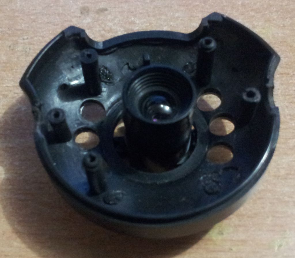
Step 2: Opening the webcam
First, open up your camera. But be careful, beware of damaging the CMOS sensor.
You need to extend the capture button wires to get still images. I also took out the wires to turn on / off the LEDs. They were gray and yellow flowers(Your may differ). 
Step 3: Working with the lens
Now we need to flip the lens over the CMOS sensor. Place it 2-3 mm from this sensor and secure (eg with superglue).
Step 4: Assembling the Camera
After flipping the lens, assemble the camera back. Now it is ready to be used as a microscope.
Step 5: Final Stage
Now you need to fix the camera on the box, as shown in the photo. Now it's ready to receive images!You can also put a mirror so that the light spreads throughout the "object of study" and under it. Now our microscope is completely ready!

Several pictures taken with this webcam/microscope


Enjoy! ;)
In general, I got tired of looking at SMD elements with a magnifying glass, marking on them and inspecting the tracks for damage and soldering quality. Plus, one hand is always busy. Someone will say about binocular glasses, SW. glass on a stand ... Binoculars are far from the best solution, vision sets quickly from them + the quality is far from ideal, of those that have ever been felt. (There is an idea to close binoculars with a lens from a currency detector. But this is still only an experiment at the mock-up stage.) Magnifying glass on the stand often interferes and is not always convenient + distorts a little at the edges. You can use a microscope, but it does not fit with large boards. Yes, and not a cheap toy. As well as factory cameras for such cases. So it will be as always ... We will do it ourselves
I bought the cheapest webcam from those that were. Like for 35 UAH ($4.37). I took another dead one from a friend for donor parts. Here is such a purely Chinese webcam:


Next, we unscrew the lens from the donor and remove all lenses from it. Instead of native lenses, I tried to attach a lens from a CD drive (I did not try it from a DVD drive, it is very small in diameter there). We screw it into the webcam, we [one focus ... The result did not fit. Since I was not going to do an optical sight. At a distance of about half a meter, small numbers and letters were visible on a sticker from an old hard drive stuck on the wall. Photo for example:


And when the lens was removed from the camera itself, it increased it to greater distances ... In principle, such a result may also come in handy in the future.
Further, after searching through the boxes, an eyepiece from a microscope or something similar was found. Previously, he looked at the markings on SMD. For a test, I attached it to the "thermosnot", (In this moment the eyepiece is rigidly fixed in the body of the old lens. Slightly adjusted the inner diameter and planted with an interference fit. Plus, I shortened the very body of the old lens from the side of the webcam) Now the result suited me 100%. Photo of what happened:


The log in the frame is the tip of a wooden toothpick
Photo of the lens and lens (Bottom is native, without alterations. On the right, the lens is from the CD drive).

It remains to make a rigid tripod on the wall, turn the camera board in the case so that it shows adequately. Throw out the native cable and solder a thin one. And then the native is hard and thick. Well, attach a normal backlight, otherwise the native only interferes. If you return the native lens to its place, then you can use the webcam for its intended purpose
If you use a webcam with more the best performance, then the image will be of better quality. Once I got my hands on a digital soap box with a webcam function. It's a pity I don't remember the brand and model. It would be possible to use it in the same version.
By the way, if you attach such an eyepiece or a lens from a CD to a phone camera, you will get a similar result. The Chinese are already churning out cases with a lens for iPhones. Came across me recently Chinese store. Probably they ripped off the idea from my contact. I did that a year and a half ago on an old Nokia
I did this procedure six months ago, but today, to describe it, I “sorted it out” what and how it happened then.
Due to the crazy pace of development of radio engineering and electronics towards miniaturization, more and more often, when repairing equipment, one has to deal with SMD radio components, which, without magnification, are sometimes impossible even to consider, not to mention accurate installation and dismantling.
So, life forced me to search the Internet for a device, such as a microscope, which could be made by hand. The choice fell on USB microscopes, of which there are a lot of homemade products, but all of them cannot be used for soldering, because. have a very short focal length.
I decided to experiment with optics and make a USB microscope that would suit my needs.
Here is his photo:

The design turned out to be rather complicated, so it makes no sense to describe in detail each manufacturing step, because. this will greatly clutter up the article. I will describe the main components and their step-by-step production.
So, "without spreading the thought along the tree", let's start:
1. I took the cheapest A4Tech webcam, to be honest, they just gave it to me because of the shitty image quality, which I didn’t care about, as long as it was in good working order. Of course, if I took a better and, of course, expensive webcam, the microscope would turn out with best quality image, but I, like Samodelkin, act according to the rule - “For lack of a maid, they “love” the janitor”, and, besides, the image quality of my USB soldering microscope suited me.


I took a new optic from some kind of children's optical sight.


To mount the optics in the bronze bushing, I drilled two ø 1.5 mm holes in it (sleeve) and cut the M2 thread.

I screwed M2 bolts into the threaded holes, on the ends of which I glued beads for easy unscrewing and tightening, in order to change the position of the optics relative to the pixel matrix in order to increase or decrease the focal length of my USB microscope.
![]()


Next, I thought about lighting.
Of course, it was possible to make an LED backlight, for example, from a gas lighter with a flashlight that costs a penny, or from something else with self-powered power, but I decided not to clutter up the design and use the power of the webcam, which is supplied via a USB cable from the computer .
To power the future backlight, from the USB cable that connects the webcam to the computer, I brought out two wires with a mini-jack (male) - “+ 5v, from the red wire of the USB cable” and “-5v, from the black wire”.


To minimize the design of the backlight, I decided to use LEDs, which I soldered from the LED backlight tape from the broken laptop matrix, fortunately, I had such a tape in my “stash” for a long time.

Using scissors, a suitable drill and a file, I made a ring of the right size from double-sided foil fiberglass and, cutting out tracks for soldering LEDs and quenching SMD resistors with a nominal value of 150 ohms on one side of the ring, (I put a 150 ohm resistor in the gap of the positive power wire of each LED ) soldered our backlight. To connect the power from the inside of the ring, I soldered a mini-connector (mother).


To connect the backlight to the lens, I used a round threaded nut (not used for attaching lens glasses), which I soldered to the inside of the backlight ring (that's why I took double-sided fiberglass).

So, the electron-optical part of the USB microscope is ready.


Now you need to think about the movable mechanism for fine-tuning the sharpness, the movable tripod, the base and the work table.
In general, it remains to come up with and create the mechanical part of our homemade product.
Go…
2. As a movable mechanism for fine-tuning the sharpness, I decided to take an outdated mechanism for reading floppy disks (popularly called the "flop drive").
For those who did not find this "miracle of technology", it looks like this:


In short, after a complete disassembly of this mechanism, I took the part that was responsible for the movement of the reading head, and after mechanical refinement (trimming, sawing and filing), this is what happened:


To move the head in the floppy drive, a micromotor was used, which I disassembled and took only the shaft from it, fixing it back to the movable mechanism. For the convenience of rotating the shaft, on its end, which was inside the engine housing, I put on a roller from the scroller of an old computer mouse.
Everything turned out as I wanted, the movement of the mechanism was smooth and accurate (no backlash). The movement of the mechanism was 17 mm, which is ideal for fine-tuning the sharpness of the microscope at any focal length optics.
With the help of two M2 bolts, I fixed the electron-optical part of the USB microscope to a movable mechanism for fine-tuning the sharpness.


Creating a movable tripod did not cause any particular difficulties for me.
3. Since the times of the USSR, the UPA-63M enlarger was lying in my barn, the details of which I decided to use. For the tripod stand, I took such a ready-made rod with a mount, which was included in the enlarger kit. This rod is made of aluminum tube with outer ø 12 mm and inner ø 9.8 mm. To attach it to the base, I took an M10 bolt, screwed it to a depth of 20 mm (with force) into the bar, and left the rest of the thread by cutting off the bolt head.


The mount had to be slightly modified in order to connect it with the parts of the microscope prepared in step 2. To do this, I bent the end of the mount (pictured) at a right angle and drilled a hole ø 5.0 mm in the bent part.


Further, everything is simple - with an M5 bolt 45 mm long, through the nuts, we connect the pre-assembled part with the mount and put it on the rack, securing it with a locking screw.


Now the base and table.
4. For a long time I had a piece of translucent light brown plastic. At first I thought it was plexiglass, but upon processing I realized that it was not. Well, oh well - I decided to use it for the base and stage of my USB microscope.

Based on the dimensions of the previously obtained design, and the desire to make a large table for reliable fastening of boards during soldering, I cut out a rectangle 250x160 mm in size from the existing plastic, drilled a hole ø 8.5 mm in it and cut an M10 thread for attaching the rod, as well as holes for fixing the base of the table.


I glued the legs to the bottom of the base, which I cut out from the soles of old shoes with a homemade drill.

5. The table was machined on a lathe (on my former enterprise, I, of course, do not have a lathe, although there is a 5th category of a turner) 160 mm in size.

As a base for the table, I took a leveling stand


, poultry farming")


- Burns, Robert - short biography
- The concept of common vocabulary and vocabulary of limited use
- Nancy Drew: The Captive Curse Walkthrough Nancy Drew Curse of Blackmoore Manor Walkthrough
- Deadpool - Troubleshooting
- Won't start How to Survive?
- What to do if bioshock infinite won't start
- Walkthrough Nancy Drew: Alibi in Ashes
- Spec Ops: The Line - game review, review Spec ops the line crashes on missions
- Room escape level 1 walkthrough
- Processing tomatoes with boric acid How much will 2 grams of boric acid
- Cucumber Grass (Borago)
- Bioinsecticide Lepidocid: purpose, properties and application procedure Lepidocide waiting period
- How to change the language to Russian in steam
- Dendrobium noble: room care
- Morphology of plants general concepts - document
- Planting, propagation and care of bamboo at home, photo Growing bamboo from seeds
- How to strengthen the cellular signal for the Internet in the country
- Sanskrit reveals the forgotten meaning of Russian words (2 photos)
- The oldest language Sanskrit programming language of the future Dead language Sanskrit
- Who has dominion over all the earth?